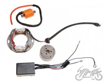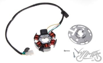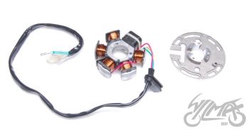




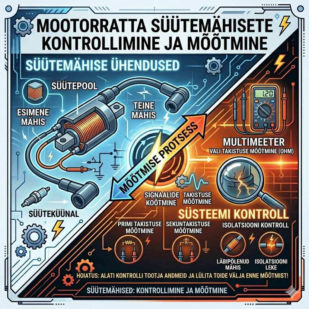
A motorcycle or ATV stator is part of the charging and ignition system. It produces alternating current voltage as the engine spins, which is then used to charge the battery, power electrical loads, and, on some machines, supply the ignition system. Measuring a stator correctly requires more than simply checking for voltage at the battery.
A stator can fail in several ways: open windings, shorted windings, short-to-ground faults, weak output under load, or heat-related failure.
This guide explains how to test motorcycle and ATV stators using a multimeter and basic electrical checks.
1. What the Stator Does
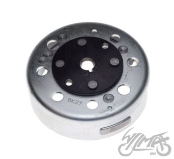
The stator is a stationary set of copper windings mounted inside the engine cover. A rotor or flywheel with magnets spins around it. As the magnets pass the windings, AC voltage is generated.
Most powersport stators fall into a few common types:
Charging Stator
Produces AC voltage for the charging system. The AC voltage goes to the regulator/rectifier, which converts it to DC and limits voltage to charge the battery.
Three-Phase Stator
Common on many street bikes, sport bikes, UTVs, and larger ATVs. Usually has three yellow or white wires coming from the stator.
Single-Phase Stator
Common on smaller motorcycles, dirt bikes, scooters, and ATVs. Usually has two charging output wires, though wire colors vary.
Lighting Coil / Accessory Coil
Some off-road bikes and ATVs have separate windings for lights or accessories.
Source / Exciter Coil
On some CDI ignition systems, the stator also has a coil that powers the ignition box.
Pickup / Pulse Coil
This is technically not the charging stator, but it is often located on or near the stator assembly. It tells the ignition system when to fire the spark.
2. Tools Needed
To measure a stator, you will need:
- Digital multimeter
- Service manual or wiring diagram
- Back probes or small test leads
- Socket tools to access connectors
- Fully charged battery
- Optional: clamp meter, insulation tester/megohmmeter, oscilloscope
A standard multimeter is enough for most basic stator tests.
3. Safety Precautions
Before testing:
- Work in a well-ventilated area.
- Keep hands, tools, and clothing away from chains, belts, fans, and rotating parts.
- Support the ATV or motorcycle securely.
- Do not short stator wires together while the engine is running.
- Disconnect the stator connector when doing resistance tests.
- Use AC voltage mode when testing stator output directly.
- Use DC voltage mode when testing battery charging voltage.
4. Preliminary Battery Charging Test
Before condemning the stator, test the charging system as a whole.
Step 1: Measure Battery Voltage, Engine Off
Set your meter to DC volts.
A healthy fully charged 12 V battery should read around:
- 12.6–12.8 V = fully charged
- 12.3–12.5 V = partially charged
- Below 12.2 V = weak or discharged
Step 2: Start the Engine
Measure voltage across the battery terminals.
At idle, voltage may be around:
- 12.5–13.2 V, depending on machine
Raise rpm to around 3,000–5,000 rpm.
A normal charging voltage is usually:
- 13.5–14.8 V DC
If battery voltage stays near 12 V or drops while running, the charging system is not working properly.
If voltage rises above about 15 V, the regulator/rectifier may be faulty.
This test does not prove the stator is bad, but it tells you whether the charging system is functioning.
5. Stator Resistance Test
The resistance test checks the condition of the stator windings. This is done with the engine off and the stator unplugged.
Three-Phase Stator Resistance Test
A three-phase stator usually has three similar-colored wires, often yellow or white.
Label them:
- A
- B
- C
Set your multimeter to ohms.
Measure resistance between:
- A to B
- B to C
- A to C
All three readings should be nearly equal.
Typical values are often very low, for example:
- 0.1–1.0 ohm
Some larger stators may be slightly higher or lower. Always compare with the service manual.
Important Technical Note
Many digital multimeters are not very accurate at very low resistance. Touch the meter leads together first and note the reading. If the leads read 0.2 ohm, and the stator reads 0.5 ohm, the actual winding resistance may be about 0.3 ohm.
For more accurate low-resistance measurement, use:
- Relative/zero function on the meter
- Four-wire milliohm meter
- Known-good stator comparison
What the Results Mean
- ReadingPossible Meaning
- All three readings equal and in specWindings likely OK
- One pair reads open/infiniteBroken winding or connection
- One pair much lower than othersShorted winding
- One pair much higher than othersDamaged winding or poor connector
- Readings unstableBad connector, broken wire, or internal failure
Single-Phase Stator Resistance Test
A single-phase charging stator normally has two output wires.
Measure resistance between the two stator wires.
Typical readings vary widely but may be:
- 0.2–2.0 ohms for charging coils
- Higher for lighting or source coils, depending on design
Compare with the manual.
If the meter reads OL or infinite resistance, the winding is open.
If it reads nearly zero ohms, the winding may be shorted, although some high-current charging windings normally have very low resistance.
6. Stator Short-to-Ground Test
This is one of the most important stator tests.
The stator windings should normally be isolated from engine ground unless the system is specifically designed differently. Most modern charging stators should not have continuity to ground.
How to Test
With the stator unplugged and engine off:
- Set the meter to resistance or continuity.
- Place one lead on a stator output wire.
- Place the other lead on engine ground or battery negative.
- Repeat for every stator wire.
Expected Result
You should usually see:
- OL/infinite resistance
- No continuity beep
Bad Result
If any stator output wire shows continuity to ground, the stator is likely shorted.
Even a partial short to ground can reduce output and overheat the regulator/rectifier.
Technical Note: Megohm Testing
A normal multimeter uses very low test voltage. Sometimes a stator passes a basic continuity test but fails when hot or under voltage.
A more advanced test uses an insulation resistance tester, also called a megohmmeter or “megger.”
Typical insulation test voltage:
- 100 V to 500 V DC, depending on manufacturer recommendation
A good stator should usually show very high resistance to ground, often in the megohm range.
Do not megger sensitive electronic modules such as the ECU, CDI, or regulator/rectifier. Disconnect the stator completely before insulation testing.
7. AC Output Voltage Test
The AC output test checks whether the stator produces voltage while the engine is running. This is usually the best practical stator test.
The stator must be unplugged from the regulator/rectifier for this test, unless the service manual specifies otherwise.
Three-Phase AC Output Test
Set the multimeter to AC volts.
With the stator connector unplugged, start the engine.
Measure AC voltage between:
- A to B
- B to C
- A to C
Do not measure from a stator phase to ground for a normal three-phase floating stator. Measure phase-to-phase.
Typical AC Output
At idle, you may see:
- 15–30 VAC
At 3,000–5,000 rpm, you may see:
- 40–100+ VAC
The exact value depends on the machine.
The three readings should be similar. A common rule is that they should be within about 5–10% of each other.
Example
At 4,000 rpm:
- A-B = 68 VAC
- B-C = 70 VAC
- A-C = 69 VAC
This is likely good.
Bad example:
- A-B = 68 VAC
- B-C = 25 VAC
- A-C = 67 VAC
This indicates a likely weak or damaged phase.
Single-Phase AC Output Test
For a two-wire stator:
- Set the meter to AC volts.
- Start the engine.
- Measure between the two stator output wires.
Typical output:
- 15–30 VAC at idle
- 30–80+ VAC at higher rpm
Again, always compare with the factory specification.
8. Testing Source/Exciter Coils and Pickup Coils
Many ATVs and dirt bikes use CDI ignition systems. These may have extra stator-related coils.
Source / Exciter Coil
This coil generates voltage for the CDI.
Common resistance range:
- 50–500 ohms, depending on model
AC output while cranking may be:
- 20–100 VAC or more
Symptoms of a bad source coil:
- No spark
- Weak spark
- Spark disappears when hot
- Engine starts cold but dies after warming up
Pickup / Pulse Coil
The pickup coil triggers spark timing.
Common resistance range:
- 100–500 ohms
- Some models may be outside this range
Output while cranking is usually small:
- 0.2–5 VAC
A peak voltage adapter or oscilloscope may be needed for accurate testing because the pulse is brief.
Symptoms of a bad pickup coil:
- No spark
- Intermittent spark
- Misfire at certain rpm
- Tachometer signal problems on some machines
9. Heat-Related Stator Failure
A stator may pass tests cold but fail when hot. This is common when insulation breaks down after the engine warms up.
To diagnose:
- Test resistance cold.
- Run the engine until the problem appears.
- Shut off the engine.
- Quickly unplug and retest the stator.
- Compare hot readings to cold readings.
A noticeable change in resistance, continuity to ground, or AC output when hot may indicate internal winding failure.
Common heat-related symptoms:
- Battery charges when cold but not hot
- Engine loses spark after warming up
- Charging voltage drops after 10–20 minutes
- Regulator/rectifier overheats
- Stator connector melts
10. Inspecting the Stator Connector and Wiring
Do not ignore wiring. Many “bad stator” problems are actually connector or harness problems.
Inspect for:
- Melted plugs
- Burned terminals
- Green corrosion
- Loose pins
- Oil contamination
- Broken wires near the engine cover
- Poor ground connections
- Damaged insulation
High resistance in the connector creates heat. A slightly loose connector can melt even if the stator itself is good.
If a connector is burned, replace the terminals or connector body. Do not simply plug it back together.
11. Regulator/Rectifier vs. Stator Problems
A bad regulator/rectifier can mimic a bad stator. The stator makes AC. The regulator/rectifier converts AC to DC and controls charging voltage.
Signs of a Possible Bad Stator
- Low or no AC voltage from stator
- Unequal phase-to-phase AC voltage
- Open winding
- Continuity from stator wire to ground
- Burned stator windings
- Charging drops when hot
Signs of a Possible Bad Regulator/Rectifier
- Good stator AC output but low battery charging voltage
- Battery overcharges above 15 V
- Blown main fuse
- Regulator gets extremely hot
- AC voltage leaking into the DC system
- Battery boils or smells like sulfur
If the stator AC output is correct but the battery does not charge, suspect the regulator/rectifier, wiring, fuse, or battery.
12. More Technical Information
AC Voltage Increases with RPM
Stator output is directly related to rotor speed. As engine rpm increases, AC frequency and voltage increase.
The approximate electrical frequency depends on:
- Engine rpm
- Number of magnetic poles in the rotor
- Stator design
A simplified formula:
Frequency = RPM × Number of pole pairs ÷ 60
For example, a rotor with 6 pole pairs spinning at 3,000 rpm:
Frequency = 3000 × 6 ÷ 60 = 300 Hz
This is why stator AC output is not the same as household 50/60 Hz AC.
Open-Circuit vs. Loaded Voltage
When the stator is unplugged, you are measuring open-circuit AC voltage. This confirms the stator can generate voltage, but it does not fully prove it can supply current under load.
A stator can sometimes show acceptable open-circuit voltage but fail under load due to:
- Shorted turns
- Weak magnets
- Heat breakdown
- Poor winding insulation
More advanced testing may involve load testing, current measurement, or waveform analysis.
Shorted Turns
A winding can have shorted turns without being completely shorted to ground. This reduces output and causes overheating. Basic resistance checks may not detect this because the resistance change can be very small.
Clues include:
- Lower AC voltage on one phase
- Stator overheating
- Burnt smell or darkened windings
- Regulator repeatedly failing
- Charging output weak even with clean connectors
Floating vs. Grounded Stators
Many modern three-phase stators are “floating,” meaning none of the stator output wires are connected to ground. Measuring each phase to ground may give confusing readings.
Some older or simpler machines use grounded lighting coils. On those systems, one side of the coil may be connected to chassis ground by design. This is why the service manual is important.
Permanent Magnet Alternator
Most motorcycles and ATVs use a permanent magnet alternator. The rotor magnets are always energized, so the stator produces power whenever the engine spins.
The regulator controls voltage by either:
- Shunting excess current to ground
- Opening/closing the circuit electronically
- Using series regulation on some newer designs
Because excess stator power may be dissipated as heat, poor connections and weak batteries can stress the charging system.
13. Common Stator Test Specifications
These are general ranges only. Always use the service manual for exact values.
- TestCommon Result
- Battery engine off12.6–12.8 V DC
- Battery running at 3,000–5,000 rpm13.5–14.8 V DC
- Three-phase stator resistance0.1–1.0 ohm between phases
- Single-phase charging coil0.2–2.0 ohms
- Stator wire to groundOL/infinite, unless grounded design
- Three-phase AC output at idle15–30 VAC
- Three-phase AC output at high rpm40–100+ VAC
- Pickup coil resistance100–500 ohms typical
- Source coil resistance50–500 ohms typical
14. Step-by-Step Quick Test Procedure
If you want a simple diagnostic order, use this:
- Charge and test the battery.
- Check battery voltage with engine off.
- Start engine and check DC charging voltage at battery.
- If charging is low, inspect fuses, grounds, and connectors.
- Unplug stator from regulator/rectifier.
- Test stator resistance between output wires.
- Test each stator wire to ground.
- Start engine and measure AC output between stator wires.
- Compare AC readings between phases.
- If stator output is good, test regulator/rectifier and wiring.
- If output is low, unequal, open, or grounded, replace or repair the stator.
15. When to Replace the Stator
Replace the stator if:
- It has continuity to ground when it should not.
- One or more windings are open.
- AC output is low or uneven.
- It fails when hot.
- Windings are visibly burned.
- Resistance is far outside specification.
- It repeatedly causes charging failure after wiring and regulator are verified.
When replacing a stator, also inspect or replace:
- Regulator/rectifier
- Battery
- Stator connector
- Engine cover gasket
- Flywheel magnets
- Ground cables
- Main fuse and charging wires
A failing regulator or poor connector can destroy a new stator.
Conclusion
Measuring a motorcycle or ATV stator requires checking resistance, continuity to ground, and AC voltage output. A good stator should have balanced winding resistance, no unwanted ground path, and strong, even AC voltage between phases. However, stator problems can be heat-related or load-related, so a stator may pass a simple cold resistance test and still fail in real operation.
For the most accurate diagnosis, compare your measurements to the factory service manual and test the battery, connectors, wiring, and regulator/rectifier before replacing parts.